Hollow Panel Extrusion Mold Technology Guide 2026
Hollow Panel Extrusion Mold Technology: Engineering Principles, Die Types & Design Criteria for 2026

Manager, Huangshi Zhongjie Mould Co., Ltd. · Published July 24, 2026
📑 Table of Contents
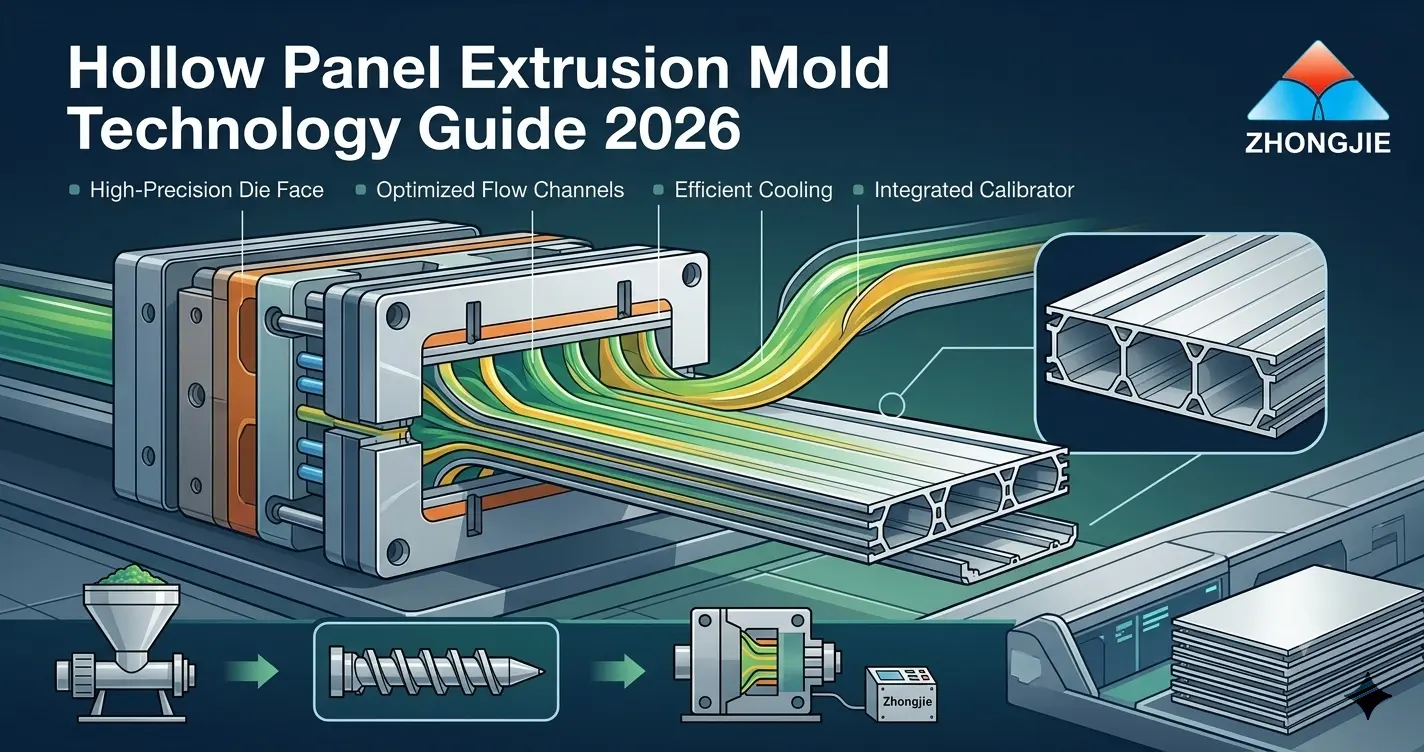
Hollow panel extrusion mold technology is one of the most engineering-intensive disciplines in plastic profile tooling. Creating a continuous, dimensionally stable panel with one or more internal chambers — while controlling weld line strength, wall thickness uniformity, and melt pressure balance across the full panel width — requires die engineering that goes significantly beyond what solid profile tooling demands. This guide examines the principles, die types, and design criteria behind hollow panel extrusion mold technology, giving engineers and procurement managers the technical foundation to specify, evaluate, and commission hollow panel tooling with confidence.
1. What Is Hollow Panel Extrusion Mold Technology?
Hollow panel extrusion mold technology refers to the engineering methods and tooling systems used to produce continuous thermoplastic panels containing one or more enclosed internal chambers — known as cells or chambers — running longitudinally along the extrusion direction. The die creates these chambers by routing molten polymer around internal steel mandrels supported inside the die body, then rejoining the split melt streams on the downstream side of each mandrel to form sealed internal walls.
The result is a panel that combines structural rigidity with reduced weight and material consumption compared to an equivalent solid cross-section. Hollow panels produced through extrusion are used across construction, interior decoration, agriculture, furniture, and industrial applications — in materials including rigid PVC, WPC (wood-plastic composite), polyethylene (PE), and polypropylene (PP). The mold technology varies by material, chamber count, wall thickness, and whether co-extrusion cap layers are required.
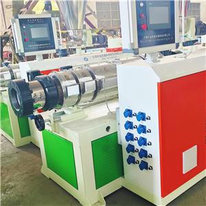
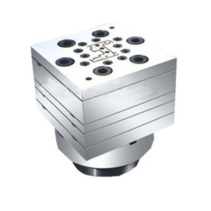
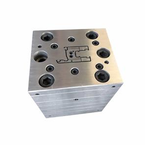
A complete hollow panel extrusion mold system consists of four matched components: the die head (melt inlet and initial distribution), the die body with internal mandrels (chamber formation and wall shaping), the die land (final dimensional stabilization before exit), and the vacuum calibrator (external sizing and cooling). Each component must be engineered as part of a unified system — not independently specified and assembled afterward.
2. Core Engineering Principles of Hollow Panel Die Design
Three fundamental engineering problems distinguish hollow panel die design from solid profile tooling. Every experienced die engineer working in this technology spends the majority of their design effort solving these three challenges before addressing secondary parameters:
2.1 Melt Flow Pressure Balance Across the Panel Width
A hollow panel die must deliver melt at equal velocity and pressure to every chamber across the full panel width — whether that width is 200 mm or 2,000 mm. Pressure imbalance causes some chambers to fill faster than others, producing panels with variable wall thickness, dimensional drift across the width, and — in severe cases — collapsed or distorted chamber walls. Achieving balance requires a precisely calculated coat-hanger or T-manifold design, with channel cross-section geometry adjusted zone by zone to equalize flow resistance across the full width.
For wide hollow panels above 600 mm, finite element analysis (FEA) of melt flow distribution is standard practice among professional die manufacturers. Designs based on experience alone — without computational validation — consistently require multiple costly trial-and-error corrections before reaching dimensional stability at production line speeds.
2.2 Weld Line Formation and Strength
Every mandrel support structure inside the die body divides the melt flow into two streams that rejoin on the downstream side. The rejoining zone — called the weld line or knit line — is inherently weaker than the surrounding extrudate because the two melt fronts must re-bond without the benefit of mechanical mixing. In structural hollow panels, weld line tensile strength typically reaches 60–85% of the parent material strength under optimized die design conditions. Poorly designed dies produce weld lines below 50% of parent strength — a structural failure risk in load-bearing applications.
2.3 Wall Thickness Uniformity at Thin Sections
Hollow panel walls — particularly the internal webs connecting outer skins — are typically 1.0–2.5 mm thick. Maintaining uniform thickness across these sections requires die gap control to ±0.05 mm at the thinnest points. Any variation in melt velocity across a thin web section produces a differential that appears as visible thickness banding when the panel is cut and inspected. Die land length at thin-wall sections must be carefully balanced: too short and melt memory causes post-extrusion distortion; too long and melt pressure drop across the thin section causes the web to under-fill.
3. Hollow Panel Profile Types and Their Mold Requirements
Hollow panel profiles used commercially span a wide range of chamber configurations and geometric complexity. The mold requirements scale with both chamber count and panel width. The table below maps the most common hollow panel profile categories to their key die engineering requirements:
| Panel Type | Typical Applications | Chamber Count | Primary Die Challenge |
|---|---|---|---|
| Twin-wall flat panel | Roofing sheets, signage, glazing | Multiple vertical ribs, 2 skins | Uniform rib spacing, outer skin flatness |
| Multi-chamber hollow decking | Outdoor decking, dock boards | 2–5 longitudinal chambers | Weld line strength, span-rated wall thickness |
| Hollow wall / ceiling panel | Interior cladding, partition walls | 3–8 chambers | Surface finish, interlock tongue-and-groove geometry |
| UPVC window hollow profile | Window frames, sash profiles | 3–6 chambers | Multi-mandrel support, thermal break geometry |
| Agricultural hollow board | Greenhouse panels, livestock flooring | 4–10 chambers | Wide panel uniformity, pressure balance across 1,000+ mm |
| Co-extruded hollow panel | Premium decking, UV-resistant wall panels | 2–6 chambers + cap layer | Cap layer adhesion, secondary channel integration |
Agricultural and construction hollow panels above 800 mm in width represent the most demanding category in hollow panel extrusion mold technology. At this width, achieving uniform melt distribution across 8–12 chamber cells simultaneously — while maintaining outer skin flatness within ±0.3 mm — requires a manifold design validated by flow simulation before steel is cut. Suppliers without FEA capability or relevant wide-panel die experience should not be shortlisted for projects of this complexity.
4. Mandrel Design and Weld Line Management
The mandrel system — the internal steel structures that create hollow chambers inside the die — is the defining engineering challenge of hollow panel extrusion mold technology. Three mandrel support configurations are used in commercial hollow panel dies, each with distinct advantages and limitations:
4.1 Spider Leg Supports
Spider legs are narrow steel bridges connecting the mandrel body to the outer die wall, oriented perpendicular to the melt flow direction. They are the simplest mandrel support geometry and produce the shortest weld lines because the melt streams rejoin immediately behind each leg. Spider legs are standard in pipe and simple hollow profile dies, but in wide flat panel dies with multiple mandrels, they create alignment challenges — each leg must be positioned to avoid interfering with the flow channel of adjacent chambers.
4.2 Bridge or Torpedo Supports
Bridge supports extend upstream into the melt flow in a streamlined, torpedo-shaped profile that divides the melt stream gradually rather than abruptly. This gentler division allows the two melt fronts to develop higher interface temperature and pressure before rejoining, improving weld line strength by 10–20% compared to blunt spider leg geometry. Bridge supports are standard in multi-chamber hollow panel dies for PVC wall panels and WPC decking where weld line integrity under flexural load is a performance requirement.
4.3 Screen Pack Pre-Pressurization
In demanding hollow panel applications — particularly wide agricultural boards and structurally rated decking — a screen pack or restriction zone upstream of the mandrel section is used to raise melt pressure before flow division. Higher upstream pressure forces the two melt streams together at the weld line with greater bonding force, improving weld line strength to 80–90% of parent material in optimized designs. This technique adds die body length and increases extruder back-pressure, requiring the extruder and die head to be sized accordingly.
Weld line location within the panel cross-section is also a design variable. Experienced die engineers position weld lines at points of minimum structural stress — typically at the neutral axis of the panel in bending — rather than at the outer skin surfaces where flexural tension and compression are highest. For load-rated hollow panels, weld line position relative to the panel's structural cross-section should be confirmed with the die manufacturer before design approval.
5. Calibrator Integration for Hollow Panel Production
The vacuum calibrator for hollow panel extrusion must perform two simultaneous functions: size the outer panel surfaces to final dimensions and maintain internal chamber geometry during cooling. These two functions create competing demands on calibrator design that do not exist in solid profile or simple hollow profile applications.
External vacuum sizing pulls the outer panel skins against chilled calibrator plates, establishing surface flatness and overall panel thickness. Simultaneously, the internal air pressure inside each chamber — maintained by a controlled air supply through the die mandrel — must balance the external vacuum force. If internal pressure is too low, external vacuum collapses the chamber walls inward. If internal pressure is too high, the chamber walls bow outward, producing a panel with convex outer surfaces and oversized cross-section dimensions.
This internal pressure balance is calibrated during line commissioning and varies with line speed, melt temperature, and panel geometry. For this reason, the internal air pressure circuit — pressure regulator, flow control valve, and mandrel air tube diameter — must be specified as part of the die design, not added as an afterthought during commissioning. A die built without an integrated internal pressurization system requires field modification that rarely achieves the same precision as a factory-designed solution.
Calibrator sleeve length for hollow panels is longer than for solid profiles of equivalent thickness, because the chamber walls cool more slowly than solid sections of the same nominal thickness. A hollow wall panel of 10 mm total thickness with 1.5 mm wall sections requires a calibrator sleeve of 600–900 mm to reach dimensional stability — compared to 300–400 mm for a solid 10 mm profile of the same material. Undersizing the calibrator forces slower line speeds and undermines the hollow panel's weight-saving cost advantage.
6. Material Considerations Across PVC, WPC, and PE Hollow Panels
The three dominant materials processed through hollow panel extrusion molds each impose different demands on die design, mandrel geometry, and calibrator specification. Matching the die engineering to the material is not optional — it is the foundation of hollow panel mold performance.
| Material | Processing Temp. | Key Die Design Requirement | Weld Line Risk Level |
|---|---|---|---|
| Rigid PVC (UPVC) | 170–195 °C | Chrome-plated channels; narrow thermal window; corrosion-resistant die lip | Medium — PVC bonds reliably at correct temperature |
| WPC (PE or PVC base) | 155–185 °C | Abrasion-resistant nitrided steel; streamlined mandrel to prevent fiber accumulation at weld point | High — wood fiber disrupts melt front bonding at weld zone |
| PE (HDPE / LDPE) | 190–240 °C | Higher die thermal mass; longer land length for melt stabilization; larger internal pressurization circuit | Low — PE bonds well at weld lines under correct pressure |
| PP | 200–250 °C | High-temperature die steel; careful internal air pressure management; longer calibrator | Medium — PP weld strength sensitive to melt temperature at join point |
WPC hollow panels present the most challenging combination of material properties for hollow panel extrusion mold technology. Wood flour particles in the melt stream have lower thermal conductivity than the polymer matrix, meaning the melt front at weld lines contains localized cold spots that reduce bond strength. Mandrel geometry for WPC hollow dies must be specifically designed to maximize melt temperature and pressure at the weld zone — using torpedo-style bridge supports, upstream pre-pressurization, and die land temperature zones boosted 5–10 °C above those used for equivalent polymer-only hollow profiles.
At Huangshi Zhongjie Mould Co., Ltd., our engineering team has designed hollow panel dies across all four material families above — for wall panels, decking boards, agricultural sheets, and window profiles — over more than 16 years of continuous hollow panel mold manufacturing. Several of our senior engineers hold 20+ years of hands-on experience in hollow profile die design, including multi-chamber WPC panels and wide-format PVC building board dies exported to clients in Europe, the Middle East, and Southeast Asia.
7. Frequently Asked Questions
Q: How does chamber count affect hollow panel mold cost and lead time?
A: Each additional chamber adds one mandrel, one set of spider or bridge supports, and additional flow channel balancing work to the die. A single-chamber hollow die is roughly 20–30% of the cost of a six-chamber equivalent for the same panel width. Lead time increases by approximately 5–7 days per two additional chambers for panels up to 400 mm wide, and proportionally more for wider panels requiring FEA flow validation.
Q: Can a hollow panel die be modified to add chambers after initial manufacture?
A: Adding chambers to an existing hollow panel die requires machining new mandrel positions into the die body and redesigning the flow channel manifold — work that typically costs 60–80% of a new die. In most cases, commissioning a new die designed for the target chamber count from the outset is more cost-effective and produces better dimensional performance than modifying an existing tool.
Q: What internal air pressure is typically used to support hollow panel chambers during extrusion?
A: Internal chamber pressure for most rigid PVC and PE hollow panels ranges from 0.01 to 0.06 MPa above atmospheric — just enough to balance the external vacuum calibrator force without causing chamber wall outward bowing. The precise value is determined during commissioning for each specific combination of panel geometry, material, calibrator vacuum level, and line speed. It is not a fixed parameter and must be adjustable through a pressure regulator in the mandrel air circuit.
Q: What is the maximum panel width achievable with hollow panel extrusion mold technology?
A: Commercial hollow panel dies for agricultural and construction applications routinely achieve panel widths of 1,000–1,200 mm in PVC and PE materials. Experimental and specialist dies for greenhouse and industrial flooring panels have reached 2,000 mm. Above 800 mm, FEA flow simulation and extended commissioning time are essential — and the die must be mounted on an extruder with sufficient output capacity to maintain melt pressure across the full panel width at target line speed.
8. Conclusion & Next Steps
Hollow panel extrusion mold technology demands a level of engineering precision — in melt flow balancing, mandrel support design, weld line management, and calibrator integration — that separates specialist hollow panel die manufacturers from general extrusion tooling shops. The fundamental performance indicators of any hollow panel die — weld line strength, wall thickness uniformity, outer surface flatness, and dimensional stability at production line speeds — are determined entirely at the design and manufacturing stage. They cannot be corrected by downstream process adjustment after the die is built.
Buyers who understand the engineering principles behind hollow panel die technology are better positioned to evaluate supplier capability, specify tooling correctly, and commission production lines that reach stable output quickly. The criteria are clear: FEA-validated flow design for panels above 400 mm wide, bridge or torpedo mandrel support geometry for load-rated applications, integrated internal pressurization circuit, compound-specific steel and surface treatment, and a matched calibrator designed for hollow panel cooling dynamics.
At Huangshi Zhongjie Mould Co., Ltd., we design and manufacture hollow panel extrusion molds across rigid PVC, WPC, PE, and PP materials — from compact 3-chamber wall panel dies to wide-format multi-chamber agricultural and construction board tooling. We hold a High-Tech Enterprise Certificate and are a recognized member of the Extrusion Mould Association of Huangshi City. Every hollow panel die we ship is pre-tested on a comparable production line, with a dimensional measurement report and processing parameter sheet provided at delivery.
If you are specifying a new hollow panel die or evaluating suppliers for a hollow panel production line, contact our hollow panel extrusion mold engineering team with your panel drawing, target material, and production output requirement. We return a complete technical assessment and quotation within 48 hours.
Request a Free Hollow Panel Die Consultation →
Sources & References
The following sources were referenced in the preparation of this article: